Published date:
Tackling Flow Assurance Problems in Multi‐kilometre Subsea Pipelines
As the search for oil and gas is extended, hydrocarbon products are being discovered in more difficult to access locations, sometimes at great distances from land and at significant depths in the oceans.
Recovering that oil and gas now brings greater challenges. As a result, technology is developing quickly to provide more effective and economical methods to bring these hydrocarbons ashore for processing at an economical cost.
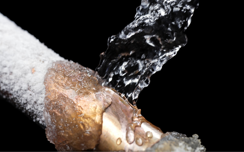
One of the challenges facing operators is the fact that oil and gas from the reservoirs needs to be maintained at elevated temperatures to prevent wax and hydrates from causing blockages in the flowline. Many crude oils contain dissolved waxes that can precipitate and deposit under the appropriate environmental conditions, whereas natural‐gas hydrates are ice‐like solids that form when free water and natural gas combine at high pressure and low temperature. This can occur in gas and gas condensate wells, as well as in oil wells. These problems are particularly relevant during a prolonged system shutdown of long tie‐backs, when no‐flow conditions exist and the flowline from the well cools to that of the surrounding sea temperature, usually around 4˚C.
One method used to overcome this problem has been to inject chemicals into the flowline to mitigate hydrate and wax formation. These chemical injection points can be at each end of the flow‐line, as well as one or more places along the flowline, depending on the seabed topography. However, in addition to the cost of designing and supplying the equipment capable of injecting these chemicals into the flowline, there is a significant cost attached downstream as a result of having to clean out these chemicals prior to refining.
A more efficient and lower cost option is to apply heat to maintain the pipeline above the temperature at which wax and hydrates can form. This is usually around 30˚C and below. Several heating solutions have been used in the past, such as skin effect current tracing (usually referred to as “skin trace” heating) and direct electric heating (DEH) which both use the actual pipeline as part of the heating circuit. However, both of these systems have proven to be inefficient and not ideally suitable for most applications. For example, as the skin effect system is primarily an inductive heating system, efficiency can be a low as 75%.
Now, another heating solution has been developed, successfully trialled and installed in the North Sea and is an efficient active heating solution to meet the challenges resulting from both deep water and shallow water applications for long heated pipelines.
The World’s first electrically trace heated, reeled, subsea pipe‐in‐pipe (ETH‐PiP) system was recently installed in the North Sea by Technip UK for Total E&P.
The Islay Project consists of an ETH‐PiP flowline carrying gas condensate from the Islay reservoir wellhead, located approximately 6km North East of the existing Forvie Manifold. It is to this manifold that the Islay pipeline is connected.
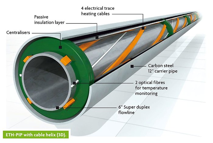
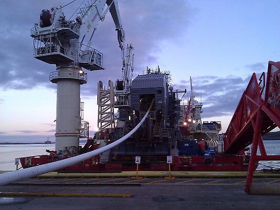
The pipeline comprises a 6” flowline inside a 12” carrier pipe. The flowline is made from Super Duplex Stainless Steel, a material best suited for aggressive environments due to its resistance to erosion, corrosion and corrosion fatigue. When completed, the 6km of ETH‐PIP was reeled onto the Apache II pipe lay vessel and subsequently laid on the seabed at approximately 100m water depth.
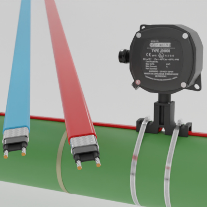
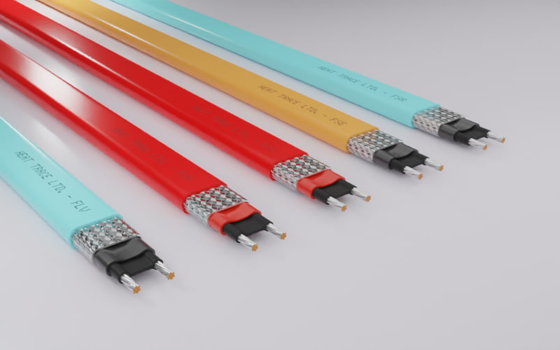
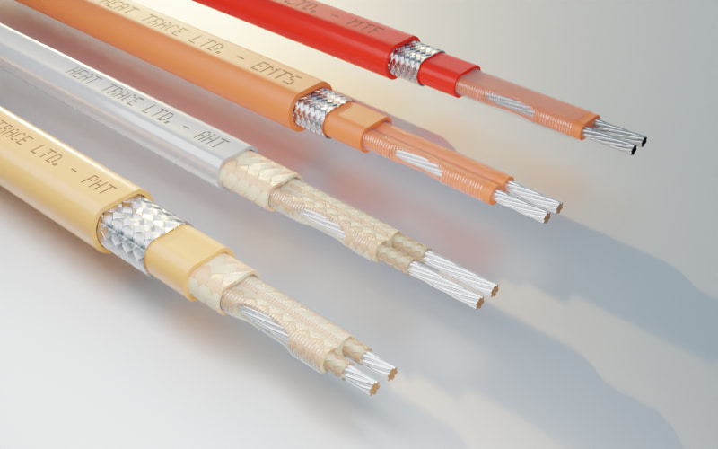
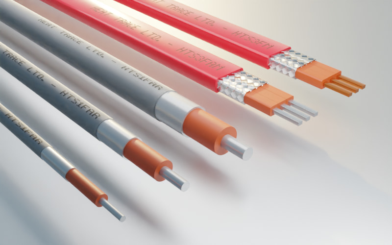
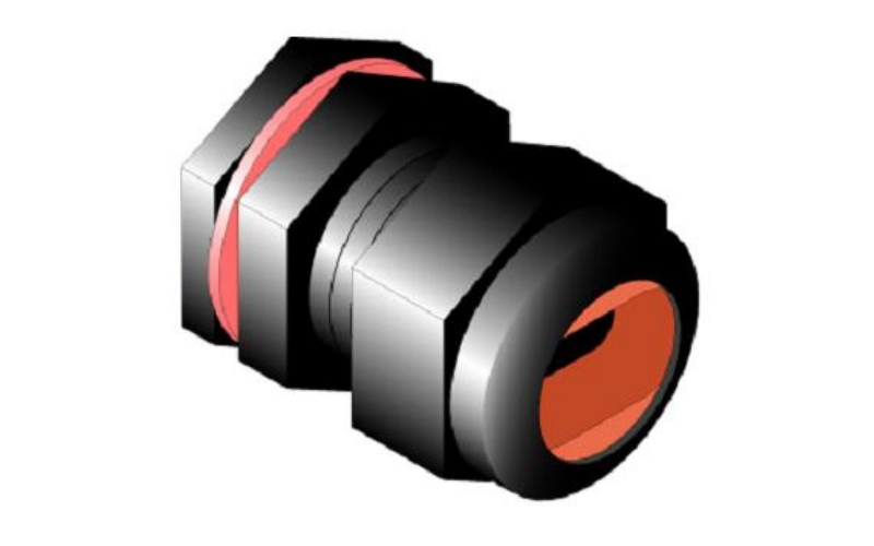
This World first electrically trace heated, reeled, subsea pipe‐in‐pipe system uses a specially modified Longline series resistance heating cable. However, the Longline system is one that has been successfully used onshore for heating multi‐kilometre pipelines for over 30 years. This particular cable features 3 individually insulated metal conductors encased within a metal braid and then an outer insulating jacket. The three conductors are designed to have a specific resistance that, together with the applied 3 phase voltage, permits each of the four heating cables which are spiralled onto the flowline, to each operate from a single supply point, producing sufficient power/heat along the entire length to maintain the pipeline at optimum flow temperatures in excess of 30˚C.
Each single three phase heating cable is capable of maintaining the desired pipeline temperature. The additional cables provide a level of redundancy, as well as ensuring that sufficient power is available to enable heat‐up of the pipeline following an extended system shutdown.
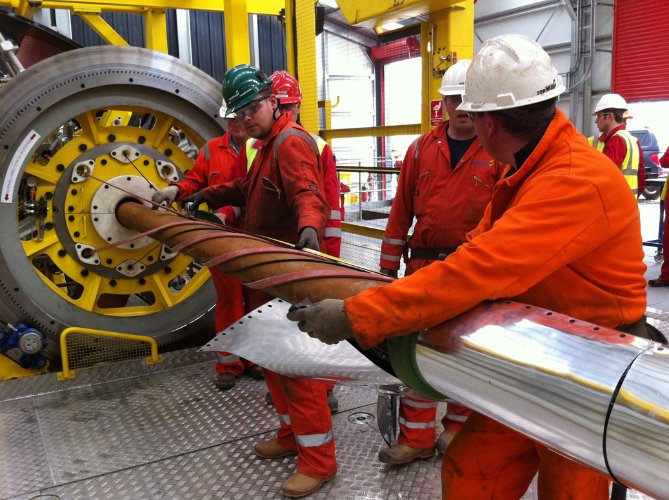
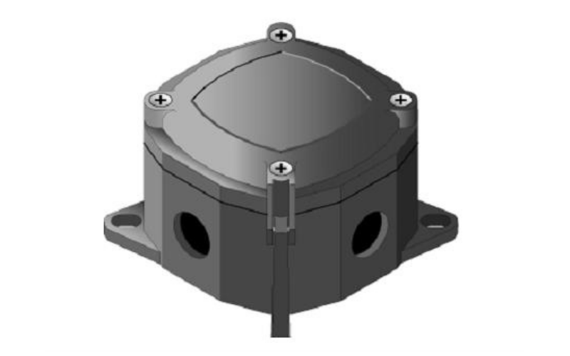
A special Cable Application Machine (CAM) was designed and built for applying the heating cables, along with fibre optic temperature control cables, to the inner flowline. Pipe centralisers were installed followed by highly efficient Aerogel passive insulation.
The completed heated and insulated flowline was then pushed inside the outer carrier pipe using a hydraulic ram assembly. The heated pipe‐in‐pipe system was pre‐fabricated in 1km pipe stalks that were welded together and the heating cables and fibre optics spliced accordingly. The 6km finished ETH‐PiP was thenreeled onto the pipe lay vessel.
Each heater circuit is connected to its own dedicated, 2000V 3‐phase power supplies. This is believed to be the highest voltage ever applied to a conventional electric heat tracing system. The design of the Islay heaters ensures that they remain flexible, allowing them to be spiralled onto the flowline so that the
ETH‐PiP can be reeled onto the pipe lay vessel.
The successful application of this heat tracing technology reduces capex and opex for fields with challenging flow assurance conditions and is expected to have a significant effect on the future of remote subsea systems.
Since the success of the Islay ETH‐PiP, developments of multikilometre pipeline heating systems have continued. There is now an extensive range of heating cables designed to meet the increasingly variable demands from offshore, inshore and onshore operators. Systems can be provided for all pipe configurations and lay methods, with projects currently being undertaken using fabricated pre‐insulated pipelines that are constructed with integral channel raceways which allows the heater to be pulled through.
The capability of Longline heaters changed when, to meet client demands, the heat tracing industry’s first continuous metal extrusion facility was designed and built. This unique facility produces virtually endless lengths of low resistance profile conductors and also continuous metallic over‐jackets. It is now possible to produce heating circuits significantly longer than existing systems, at substantially lower costs. The metallic over‐jacket results in heating cables with massively increased mechanical strength when compared with the relatively low strength of alternative systems, the technology of which demands that the conductor must not be metallically jacketed. This enables the Longline cables to be pulled greater distances without damage, thus minimising the number of field cable joints. Now, a single electrical power supply point may feed Longline circuits of around 50km, such that power supply point intervals of 100km are possible for centre‐fed heating circuits. To achieve these circuit lengths, supply voltage capabilities extend up to 6.6kV. Investment has also continued in conductor jointing techniques, recognising that joints are potentially the vulnerable point of any heating installation.
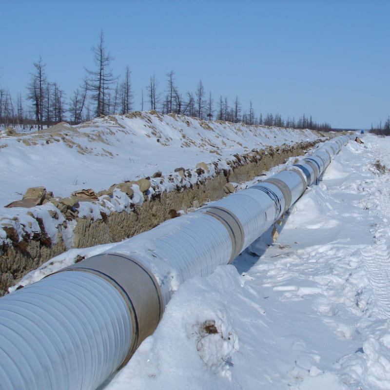
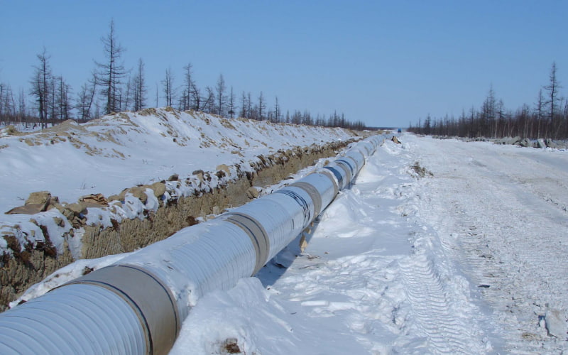
Applications now exist for heated subsea pipelines, as well as onshore buried pipelines that transport hydrocarbon products across continents over thousands of kilometres. The potentially super long heating circuits ensure a minimum number of power supply points, resulting in capex savings of many millions of dollars. The Longline heating system is easy to install without damaging or affecting the corrosion resisting pipe coating. The original Longline heating system, launched by the HeatTrace more than 30 years ago, has been refined, improved and upgraded, into a variety of heating cables, from which the most appropriate type may be selected to suit any particular application. In conclusion, these ongoing developments result in wax and hydrate mitigation systems that provide operators with efficient active heating solutions for future subsea developments. This means reservoirs previously considered as non‐cost effective can now be opened, as well as optimising hydrocarbon recovery by providing a solution offering substantial capex and opex savings when compared with alternative heating solutions.
Video explaining the use of longline heat tracing in subsea applications.

