Long Distance Pipelines (up to 50km per circuit)
The Problem
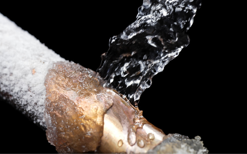
Electric Heat Tracing is commonly used around plants for temperature maintenance or freeze protection of pipework and vessels. Heat Trace Limited manufacture parallel resistance constant wattage and self-regulating cables which are convenient for in-plant applications where pipe runs are usually relatively short, perhaps a few hundred metres or less.
In refineries, chemical plants, power plants, etc., offsite pipework can often involve longer pipe runs of a kilometre or more. Heat Trace developed its LONGLINE heating system for this application where the importance is often to be able to heat the pipeline from a single electrical supply, or supplies at pipe ends only. The LONGLINE 3 phase system is capable of single circuits of upto 50 kilometres, and is a highly efficient system of proven reliability over many years.
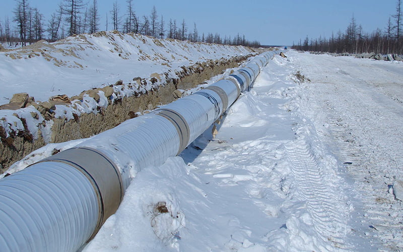
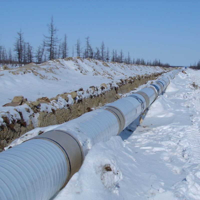
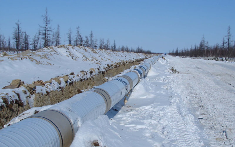
Cross-country pipes are often used to transport oils and other fluids cost effectively. These long distance pipelines sometimes require even greater heating circuit lengths, with the provision of power supplies often having the greatest expense.
For these very long pipelines, Heat Trace has introduced LONGLINE-ROUND cables, a heating system for ultra long distance pipelines. The system comprises basic components of an insulated cable contained within an continuous extruded aluminium sheath, fed from a power supply and having a control system.
LONGLINE skin effect heat tracing will usually provide the most cost effective overall heating system, both in capital and operating terms, where long distance pipelines require to be heated, whilst providing the lifetime reliability essential when the pipeline is buried below the ground.
The Solution
The Concept
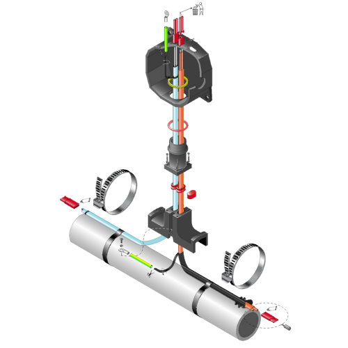
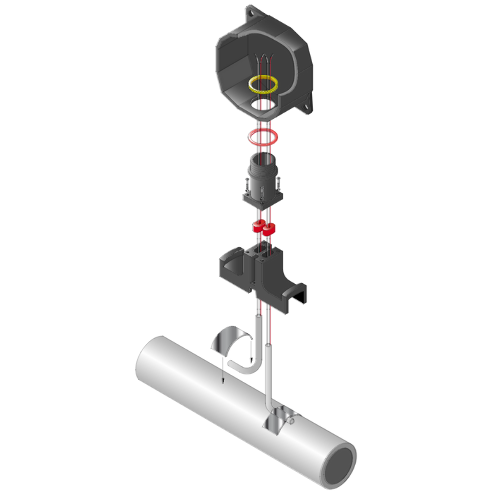
Heat is produced by the installation of three heating cables being installed along the length of the pipeline. At the remote end of the circuit, the three cables are connected together creating a star point, which completes the electrical circuit.
When AC voltage is applied to the power end, current flows through the insulated conductors creating the required heat output to match the heat losses. A combination of resistance, voltage and length will determine the power output. Heat Trace manufacture various resistances of conductor to allow a fine tuning of the power created.
For pre-insulated pipelines, it is recommended to apply three channels to the pipe before insulating. This will allow the installation of the heaters during site construction.
In addition to buried pipeline installations, LONGLINE may be provided for above ground, or underwater applications.
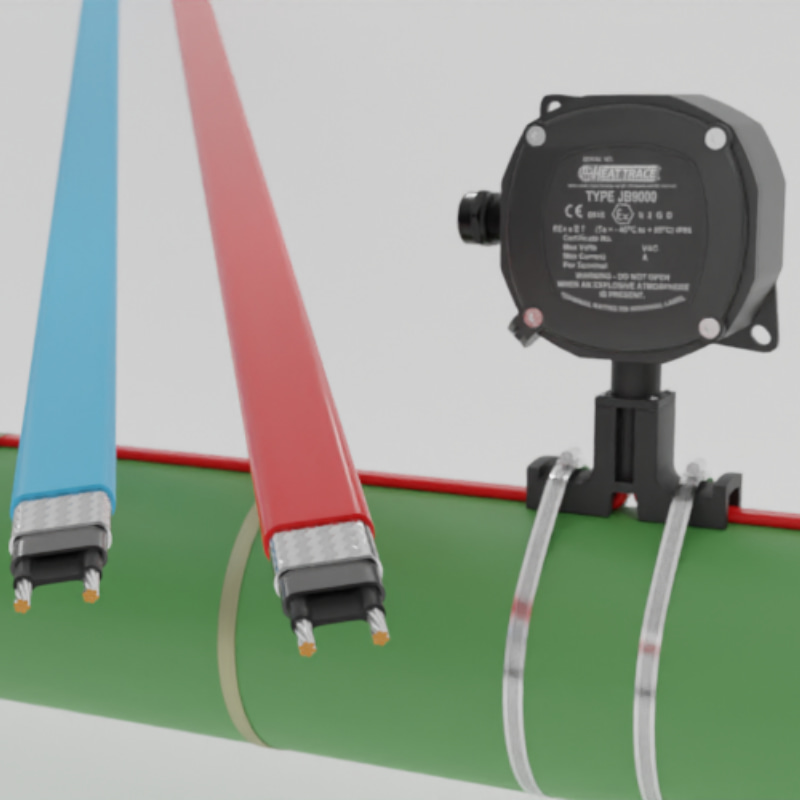
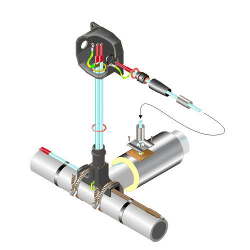
System Components
The system comprises the following basic components:-
- the insulated cables x 3
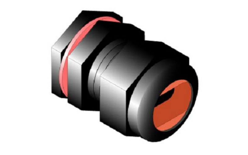
- power termination kits
- In-line splice kits
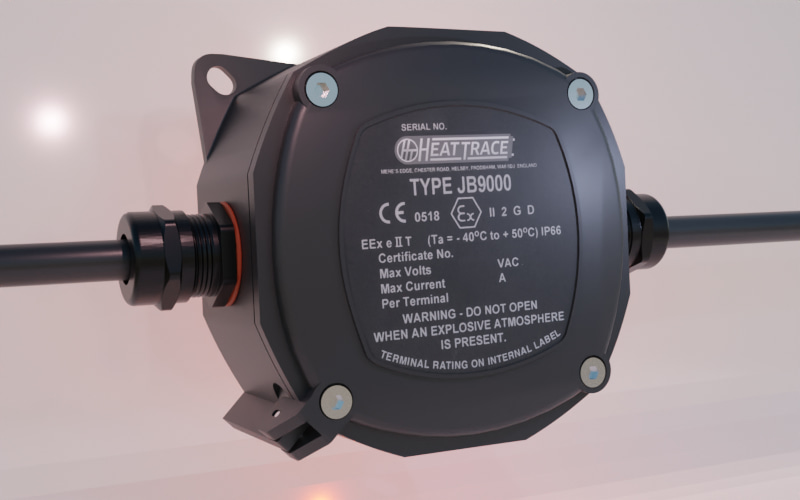
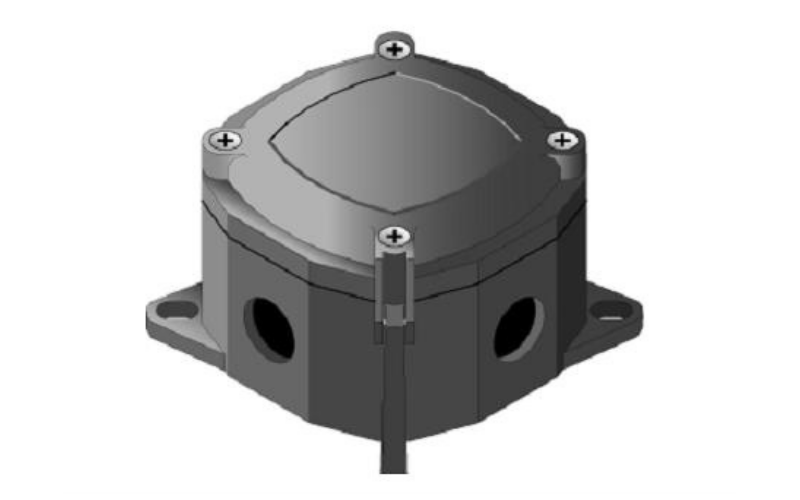
- the power supply junction box
- the remote star-end junction box
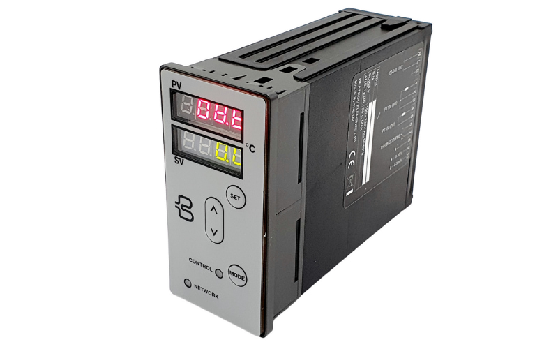
- the control/monitoring panel
View the Heat Trace Cable Range Max Exposure Temperature & Output Capability Graph:
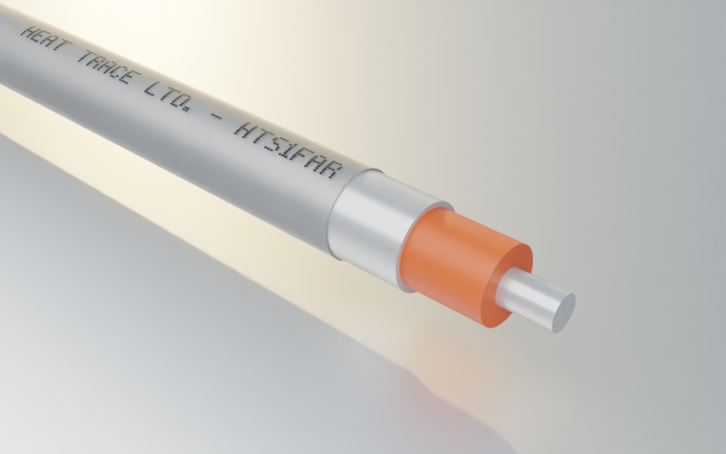
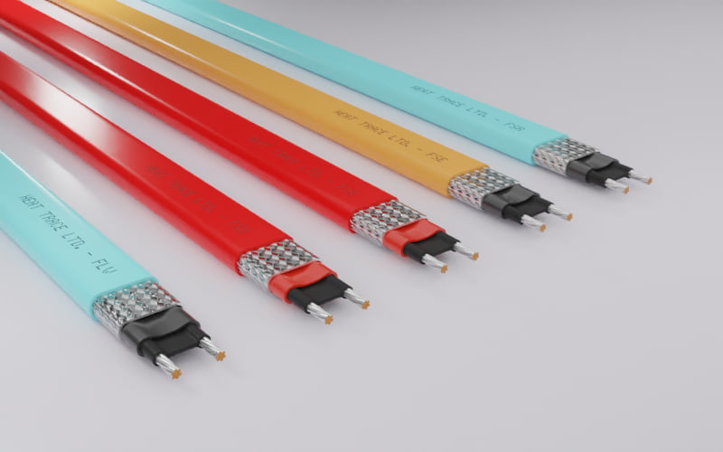
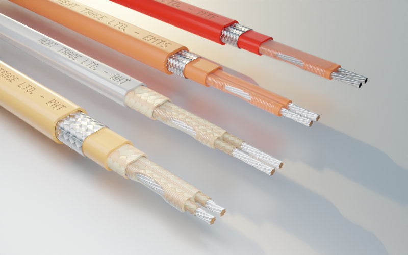
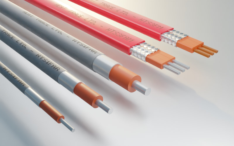
The Heating Cable
The LONGLINE cable is an aluminium or copper conductor having high temperature insulation. Heat Trace manufacture LONGLINE cable in silicone rubber followed by a continuous aluminium jacket providing mechanical protection and a waterproof layer. An optional polymer sheath can also be applied combining excellent temperature resistance and electrical properties with good mechanical strength and resistance to corrosive effects or abrasion damage during cable pulling.
The Power Supply
The power supply would usually comprise an incoming HV control cubicle.
The transformer (if required) is connected as a three phase feed, with each phase being connected to one of the three cables circuit feeds. Heat Trace Ltd have specialised in the development of control and monitoring equipment specific to heat tracing.
System Design
Heat Trace are able to provide System Design often within the framework of a turnkey contract.
Design will include heat loss computations and sizing of the LONGLINE cable. The transformer will be rated and specified, together with the control system. Where possible, our designers will try and use the available rated voltage at site (e.g. 480V, 3.3kV, etc.) to try and remove the need for a transformer.
The system will usually be designed to provide an output in the range of 15 to 100+ watts per metre (combined power over three cables).
Systems may be designed for freeze protection, temperature maintenance, or for product temperature raising duties. Pipelines may be above or below ground with thermal insulation, either as factory pre-insulated pipes, or field applied using pre-formed sections.
System documentation will normally include isometric and schematic drawings, bill of materials and components, together with provision of operating manuals.
For pipelines less tham 5km in length, please view Above Ground Pipelines

