Process Temperature Maintenance
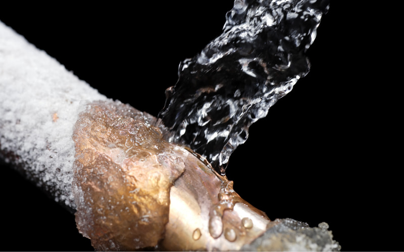
The Problem
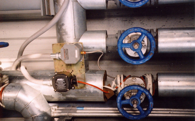
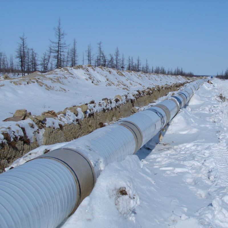
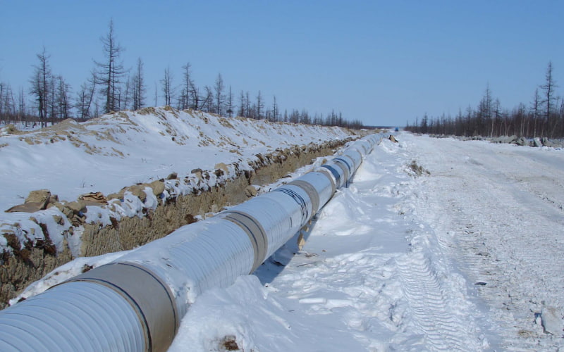
Temperature Control of complex valved piping systems, such as those around pumping sets and manifolds, can create a problem for the designer.
All pipe sections are not subjected to the same flow conditions. Often, only 1 or 2 pumps are operational whilst the remainder are in the standby/no flow condition. A temperature sensor located on a flowing pipe may de-energise tracing on static lines when heat is actually needed and vice versa.
The Solution
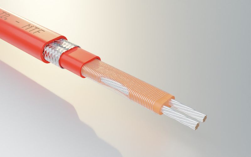
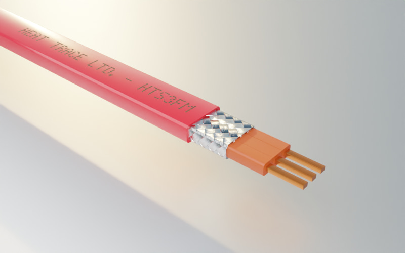
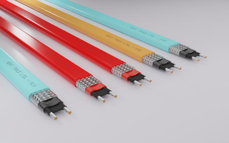
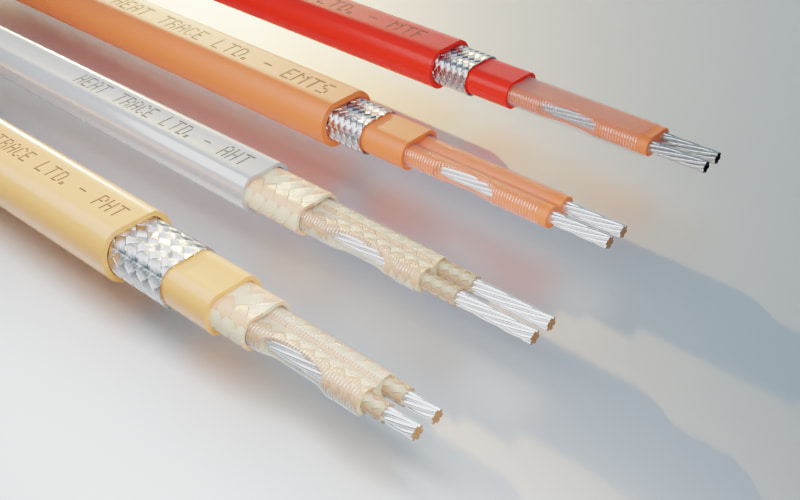
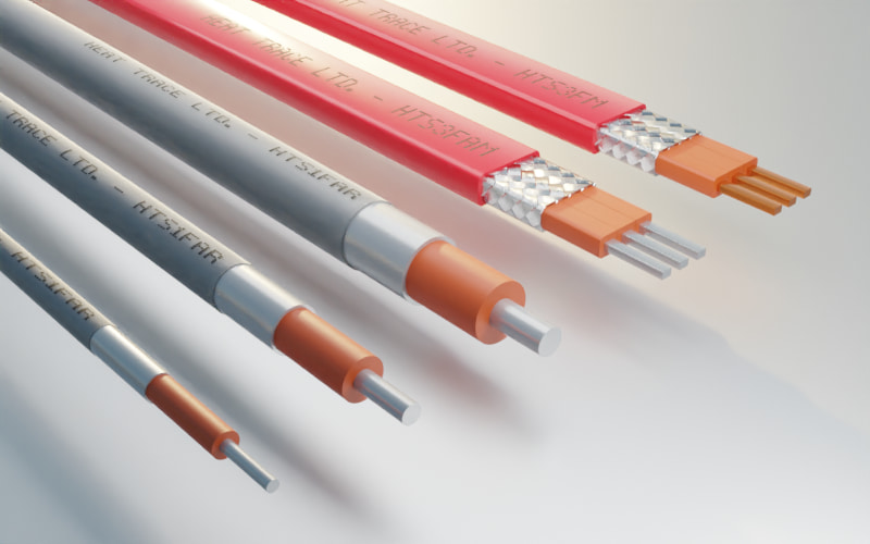
For installations less than 500m of pipework, parallel resistance self regulating (eg.Freezstop Regular) or constant power heating cables (eg. MiniTracer) are chosen which can be cut to length when required on site. When longer circuit lengths are required, series resistance cables can be used (eg. Longline).
View the Heat Trace Cable Range Max Exposure Temperature & Output Capability Graph:

Conventional Control
To correctly control a complex system from the pipe surface temeperature, each pipe section requires independant line switching. This is both expensive and complicated.
A second approach is to operate the heat tracing permanently, but uncontrolled. The system is designed to stabilise at a safe temperature, perhaps by means of self-regulating heating cables. This is excessively wasteful, as power is applied continuously when often only a small demand may exist, if at all. In such a case, line temperatures are often much higher than required, usually by 30°C, or more.
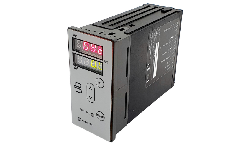
PowerMatch Control
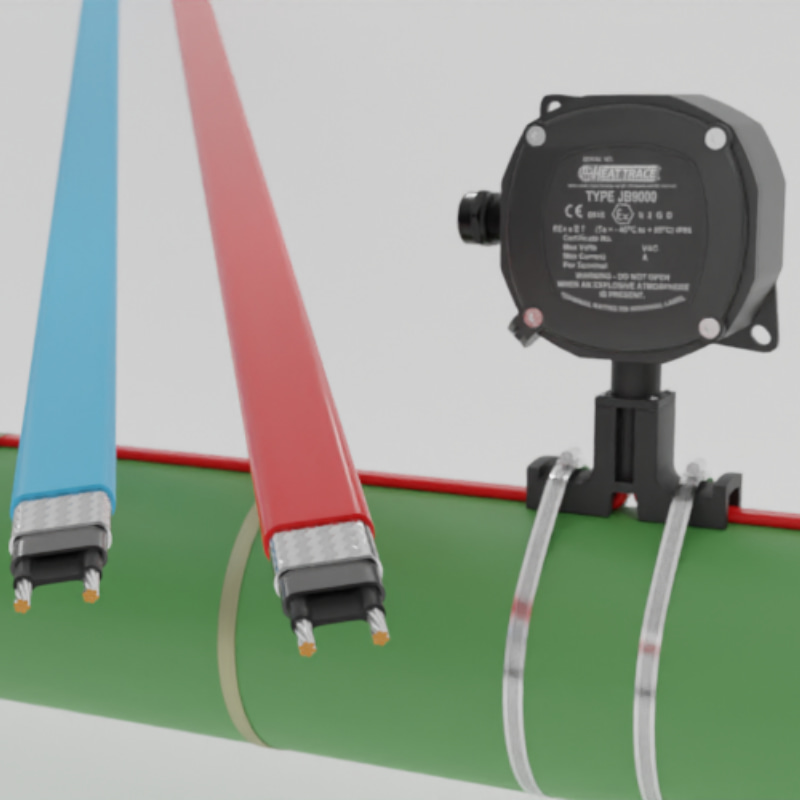
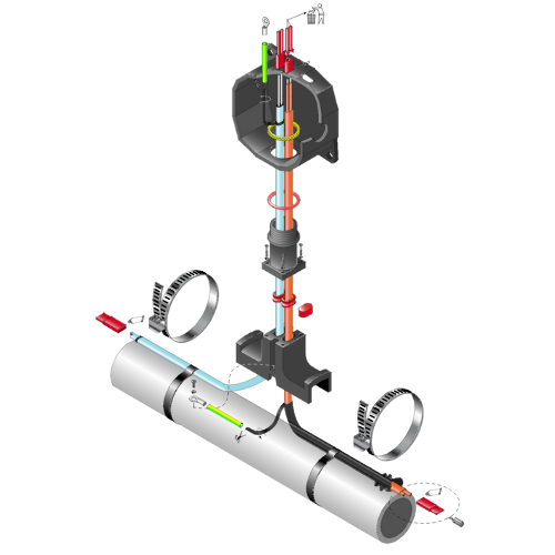
A Powermatch SELF-REGULATING SYSTEM CONTROLLER provides the best control for complex piping systems. The ambient temperature is monitored and the power output from the constant wattage heaters is adjusted to precisely match the heat losses at any given time.
When required, the Powermatch can additionally provide line control for fine tuning. The line sensor can be positioned at a point of no flow, eg, a dead leg or 'dummy' pipe.
Static lines will always receive precisely the heat needed to maintain the desired temperatures. Any unnecessary heat received by pipe sections having flow is safely removed by flowing liquid without significantly affecting its temperature.
- This design method allows complex piping systems to be controlled as a single heating circuit in a simple and effective way.
- A single Powermatch is capable of controlling large areas of process plant heat tracing, eg. 6 x 60 amp circuits, thus cabling costs are minimised.
A Powermatched constant wattage system can be continuously monitoring for correct heating function and does not suffer from high in-rush currents on start-up from cold.


